A monthly email packed with valuable content—industry news, tutorials, obsolescence updates, and more.
No sales pitches, just insights we think you'll find helpful!
A monthly email packed with valuable content—industry news, tutorials, obsolescence updates, and more.
No sales pitches, just insights we think you'll find helpful!
The two sampling techniques most commonly applied are random sampling and sequential sampling. In the random-sampling technique, no time relation exists between the timing-ramp voltage (trigger-source functioning) and the sampling instant. Owing to this, the...
Read More
The flood guns are located just outside the horizontal deflection plates. A cloud of electrons is emitted by each flood-gun cathode. These clouds are combined, shaped, and accelerated by the two control grids, as well...
Read More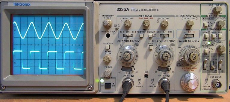
Storage oscilloscopes are used in applications where the display time at the screen is too short to examine the signals to be measured. If a single-shot signal is to be measured, only one sweep is...
Read More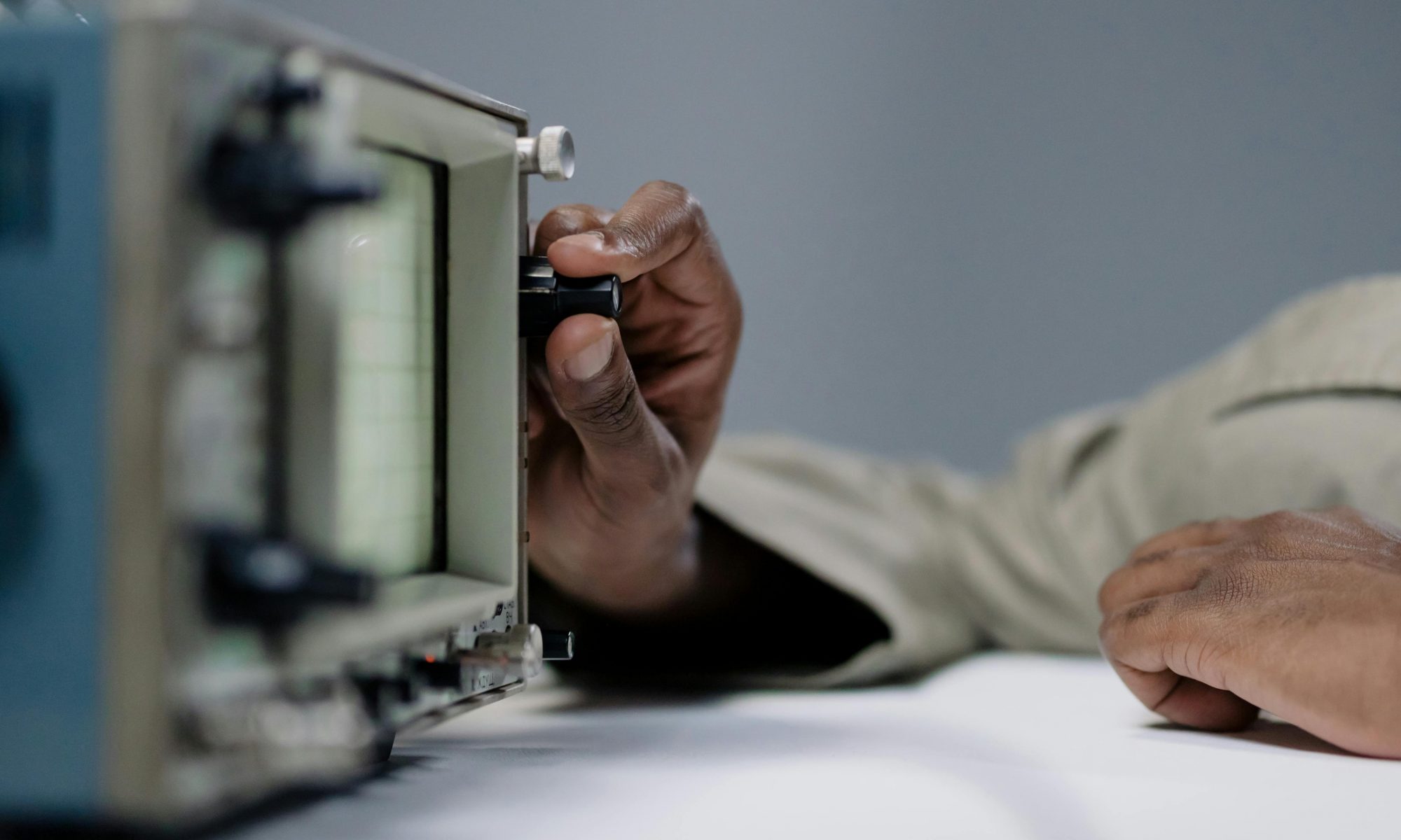
Advanced digital triggering is an incredibly useful oscilloscope feature that gives the user increased control, allowing for more stable wavelengths even when working with complex signals. In this post, we will take a look at...
Read More
Oscilloscopes are incredibly versatile tools for a diverse range of test and measurement applications. In this post, we will take a closer look at features found on many oscilloscopes: variable hold off periods and time-bases....
Read More
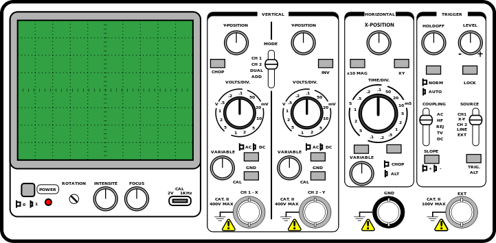
Most oscilloscopes are fitted with a switch to select the trigger source. In the case of a single-channel oscilloscope, this switch will have two positions: INT for internal triggering and EXT for external triggering. In...
Read More