A monthly email packed with valuable content—industry news, tutorials, obsolescence updates, and more.
No sales pitches, just insights we think you'll find helpful!
A monthly email packed with valuable content—industry news, tutorials, obsolescence updates, and more.
No sales pitches, just insights we think you'll find helpful!
HIL testing replicates actuality by transmitting real signals into a system from the controller into a simulated product. The controller operates at a typical pattern and does not change its behavior, rehearsing the pretended real-system...
Read More
Electromechanical systems are present in a wide range of complex and sophisticated vehicles such as ships, ground vehicles, aircraft, and the like. The way such standard systems work is through the software that operates on...
Read More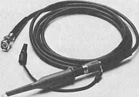
One of the probe types that can be used with an oscilloscope is a passive-voltage probe. The simplest passive-voltage probe is a coaxial cable. But what happens when a coaxial cable is linked to the...
Read More
Apart from single-shot measurements, the signal that is going to be measured must be repetitive. Signals a, b, and c in Fig. 1.9 are all repetitive because a span of time can be defined so...
Read More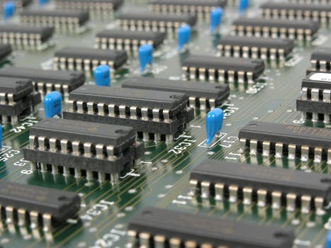
Sampling is the taking of a specimen, or a part, to illustrate the whole. For example, when a ship’s cargo of sugar must be checked for the amount (%) of water in the sugar, specimens...
Read More
Displaying readings on an analog scale, where the digital characters are printed on the scale in the different locations that the pointer swings is not an issue. But, putting digits on a digital readout where...
Read More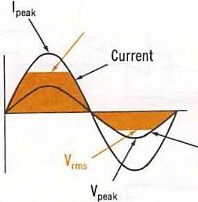
For circuit operation, the variations between de and ac functions are not too dissimilar. For de signal voltages, the individual stages of the instrument are directly coupled. Direct coupling can also be used for ac...
Read More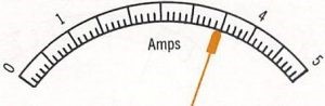
Whether you install, operate, repair, or design electrical equipment, you must know how to measure and test many types of electrical characteristics. The most imperative of these are electrical current, voltage, and resistance. Additionally, there...
Read More
Multimeters are current meters, voltmeters, and ohmmeters contained in one case. There are separate current, voltage, and resistance circuits interconnected by switches and they share the same meter movement. A function switch is utilized to...
Read More
There are many different types of amplifiers. The first type to be discussed is operational amplifiers. These are also known as op-amps. Op-amps are integrated circuits where the chip contains the transistors of the stages...
Read More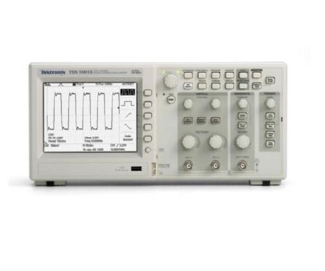
The specific characteristics of a signal can be measured by a variety of instruments. For example, a counter can measure a signal’s frequency or its period, and an ac voltmeter can measure the RMS value...
Read More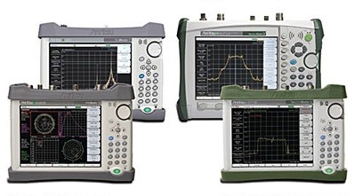
This guide will cover how-to setup Site Master: Measurement Type, Frequency, Amplitude, Markers, Limit Line, and DTF. Anritsu’s handheld cable, antenna, and spectrum analyzer family, known as the Site Master series is designed for engineer’s in-field measurements. This...
Read More