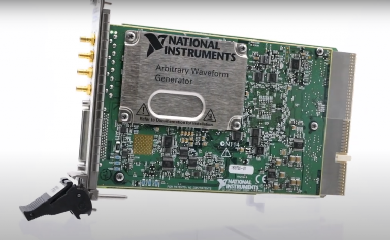
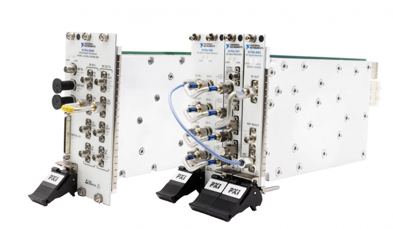
Setup and Optimize the National Instruments PXI-5441 Waveform Generator
The National Instruments PXI-5441 is a powerful PXI waveform generator designed to support high-speed waveform downloads up...
October 25, 2024
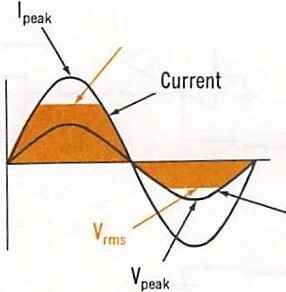
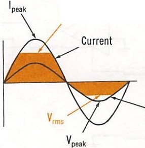
For circuit operation, the variations between de and ac functions are not too dissimilar. For de signal voltages, the individual stages of the instrument are directly coupled. Direct coupling can also be used for ac voltage signals, but typically capacitors are used to pass only the ac signal voltages from one stage to another. The test indications for ac must be handled slightly differently because of the nature of ac waveforms and the different ways of describing their levels. One ac wave has average, effective (RMS), and peak values. The analog meter movement responds to the average ac value, but we all use the effective or RMS value to describe a waveform, such as 120-V ac line power. The ac meter is calibrated for the effective value, even though it reacts to the average value.
For greater accuracy, ac signal voltages are first rectified into dc voltages for measurement. This section will describe where and how these rectifier circuits interact with the amplifier stages. Ac signal circuits usually use capacitors to couple the test signals from one stage to the next, although they are not necessary, ac voltages can be amplified by a deamplifier, but ac amplifiers are less prone to drift than de amplifiers. Also, many circuits under test could have ac signals occurring on a de level, and reading them both directly could give misleading results. Capacitors will pass ac signals while blocking dc signals so that the ac test voltage or current can be accurately measured. The capacitors are generally part of the input line to the voltage input network and the input to the first amplifier stage or follower circuit. The capacitors can also be used between the other amplifier stages, but do not have to be since the ac voltage will have already been separated. Since the capacitors must be inserted by the ac/ dc function switch, too many capacitors to be switched in numerous locations could cause wiring issues.
A capacitor is not used for ac current measurements until after the current input network converts the ac test current to an ac test voltage.
Ac to dc rectifier circuits function the same way when they are part of the amplifier stages. One diode is generally used for half-wave rectification, and four diodes, arranged as a bridge network, can be set up for full-wave rectification. A diode can be used as a rectifier because it is only effective in passing current in one direction. It passes only one half of each cycle, and the average level of the passed pulses drives the meter. The full-wave rectifier passes both halves of the waveform, but in only one polarity. This produces twice as many de pulses as the half-wave rectifier. In either case, though, the meter dial is calibrated to read the corresponding effective or RMS value.
If charging capacitors are used with the rectifiers, they will charge up to the peak value of the ac wave; but, again, the dial can be calibrated for RMS values.
A monthly email packed with valuable content—industry news, tutorials, obsolescence updates, and more. No sales pitches, just insights we think you'll find helpful!
The National Instruments PXI-5441 is a powerful PXI waveform generator designed to support high-speed waveform downloads up...

Companies in almost every industry are being transformed by artificial intelligence, and autonomous machines are...
The PXIe Platform from National Instruments offers an incredibly valuable toolset for test and measurement innovation. Its...

It is no secret that simulation and testing is an important part of designing circuits....