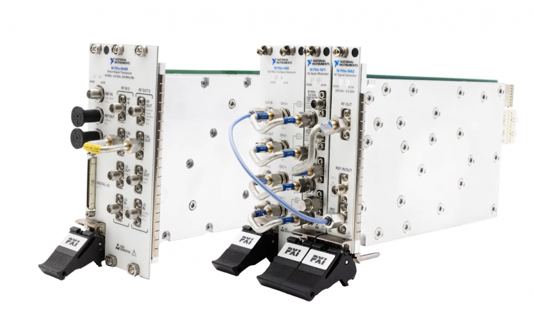
Setup and Optimize the National Instruments PXI-5441 Waveform Generator
The National Instruments PXI-5441 is a powerful PXI waveform generator designed to support high-speed waveform downloads up...
October 25, 2024
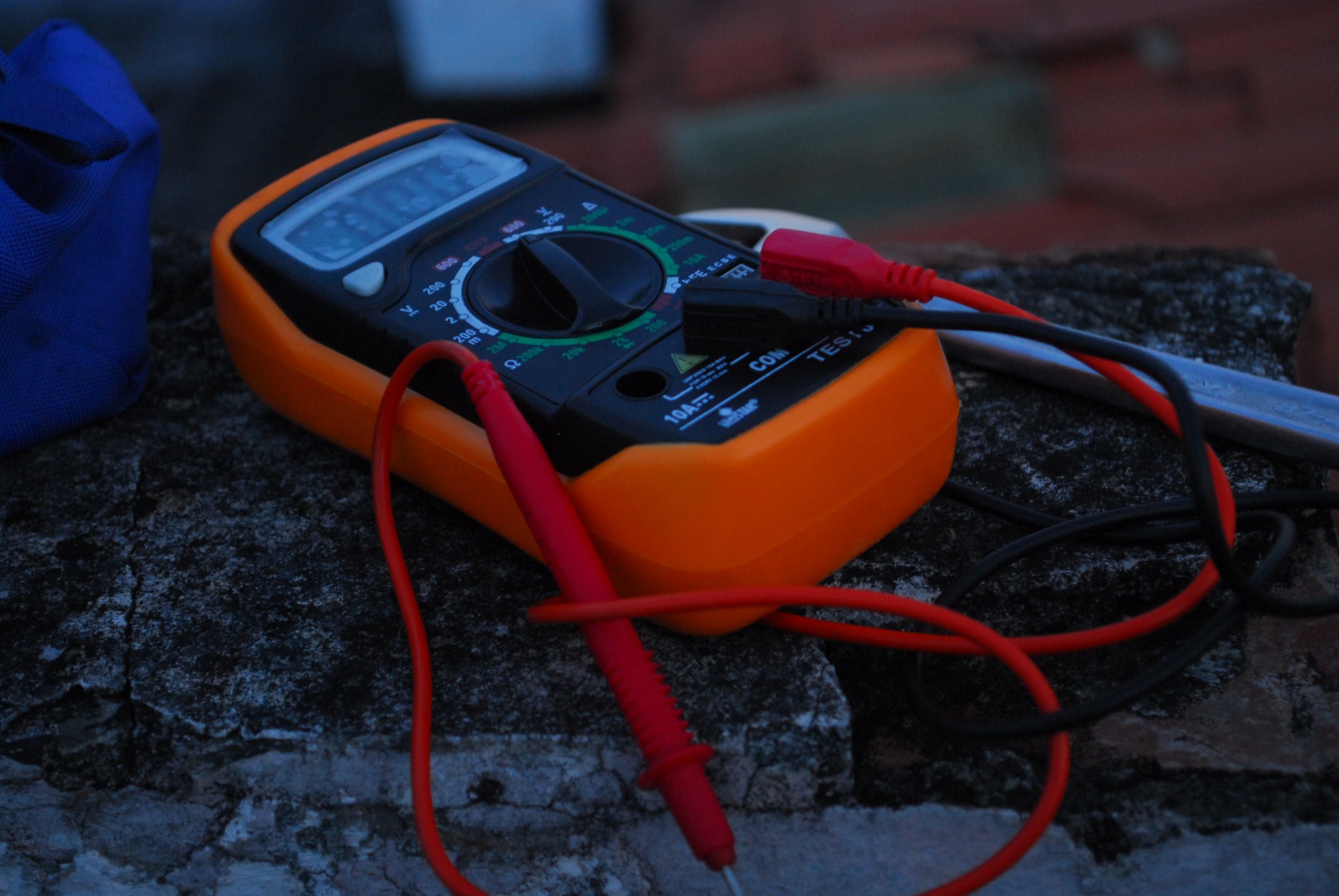
To use the meter movement to make voltage and resistance measurements, the use of Ohm’s law is required so the current flow reading can be interpreted in terms of voltage or resistance. The amplified analog meter differs because the amplifier is voltage sensitive. As explained for amplified voltage measurements, a high input resistance is used with a range switch to tap down the voltage applied to the input of the amplifier stage. Since the amplified meter is a voltage sensitive device, the input circuit used for current measurements must convert the current to corresponding voltage levels and use Ohm’s law to interpret the related current flowing in the circuit under test.
The input circuit for the amplified voltmeter needs a high resistance level, so it doesn’t load down the circuit it is connected across. The input circuit for the in-line amplified ammeter must have as low a resistance as possible since it is connected into the circuit being tested. Ideally, the input circuit should have zero ohms to keep from disturbing the circuit at all. But to be practical, some resistance must be inserted into the circuit so the current flowing through it will produce a small voltage drop that can be amplified and measured. The amount of voltage drop generated is related to the amount of current flow producing it.

The input circuit for the amplified voltmeter explained before worked as a voltage divider, with a range switch set up to apply about 0.5-volt signal input to the amplifier for each range position. A similar action must be performed by the input circuit of the amplified ammeter. The input network, though, is not a voltage divider, but is a group of high-precision, low-ohm resistors that can be connected in different combinations by the range switch to produce about 0.5-volt signal level for each range setting, as determined by Ohm’s law.
Since the current being measured is initially converted to a signal voltage, the amplifiers utilized in the amplified ammeter can be the same as those used in the amplified voltmeter. There can be differences, since the input circuit of the voltmeter must be a high resistance, while the input circuit of the ammeter must be a low resistance. The FET follower circuit was used as the first stage in the voltmeter because its high input resistance would not load down the input network as would a junction transistor. Since the ammeter input circuit uses low resistances, a junction transistor can be used with little loading effect. Usually, for simplicity’s sake, the same amplifier stages are used for both meter measurements since the same signal voltage can be used.
Sources:
https://www.electronics-tutorials.ws/amplifier/amp_1.html
https://www.kele.com/content/blog/using-a-multimeter-series-current-measuring-basics
A monthly email packed with valuable content—industry news, tutorials, obsolescence updates, and more. No sales pitches, just insights we think you'll find helpful!

The National Instruments PXI-5441 is a powerful PXI waveform generator designed to support high-speed waveform downloads up...

Companies in almost every industry are being transformed by artificial intelligence, and autonomous machines are...
The PXIe Platform from National Instruments offers an incredibly valuable toolset for test and measurement innovation. Its...

It is no secret that simulation and testing is an important part of designing circuits....