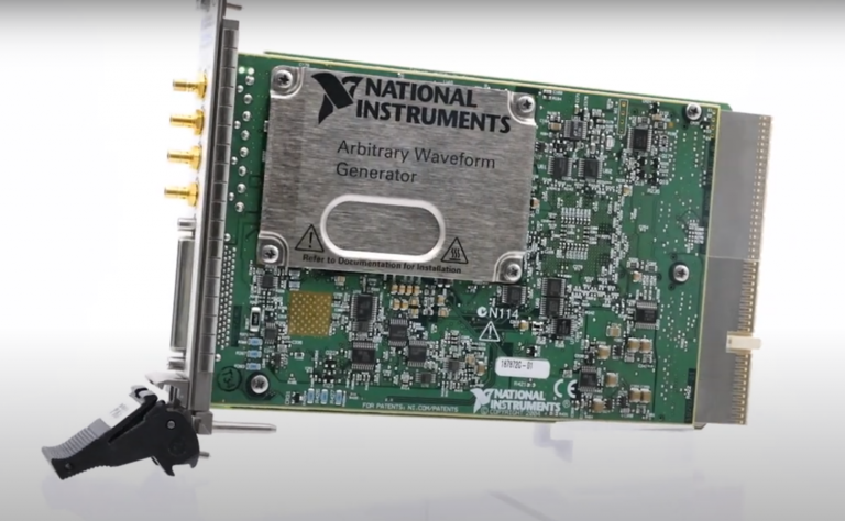
Setup and Optimize the National Instruments PXI-5441 Waveform Generator
The National Instruments PXI-5441 is a powerful PXI waveform generator designed to support high-speed waveform downloads up...
October 25, 2024
PULSE DEFINITIONS
In digital techniques, it can happen that two pulses appear in a timerelated sequence, but that the second pulse appears a little later, with a delay, with respect to the first one.
If in one signal the successive pulses do not have the same repetition time, it is said that the signal has jitter.
BANDWIDTH VERSUS RISE TIME (BTr = 0.35)
The bandwidth denotes one of the characteristics of an amplifier and the phase another characteristic. The effect of both can be studied by applying an “ideal” square-wave pulse to the input of the amplifier and studying the output voltage. This can be understood if one considers the square wave as being composed of a series (infinite) of sine waves. For example, imagine a pulse is approximated by 5 harmonics, each with its own amplitude and mutual phase. For an exact replica of the waveform, infinite harmonics are needed. The formula for the waveform is given by the Fourier analysis
V(t) = v4
1T
(sin wt + ½ sin 3wt + !- sin 5wt + · · ·)
After amplification with a factor A, the output voltage V0(t) will be
V (t) = A · 4
(sin wt + ½ sin 3wt +! sin 5wt + · · ·)
0 V
1T
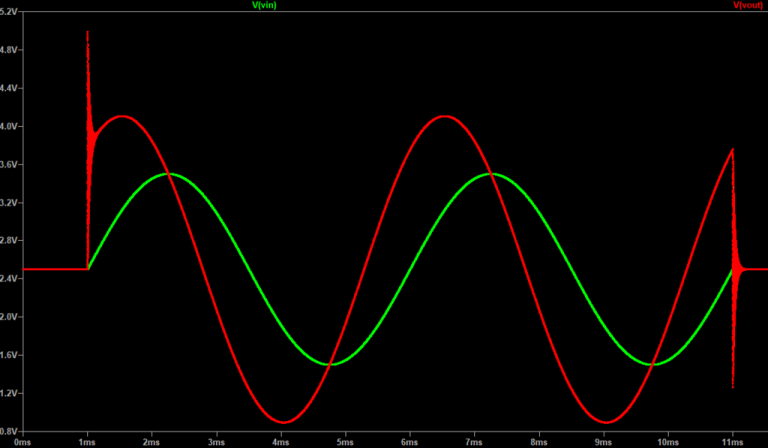
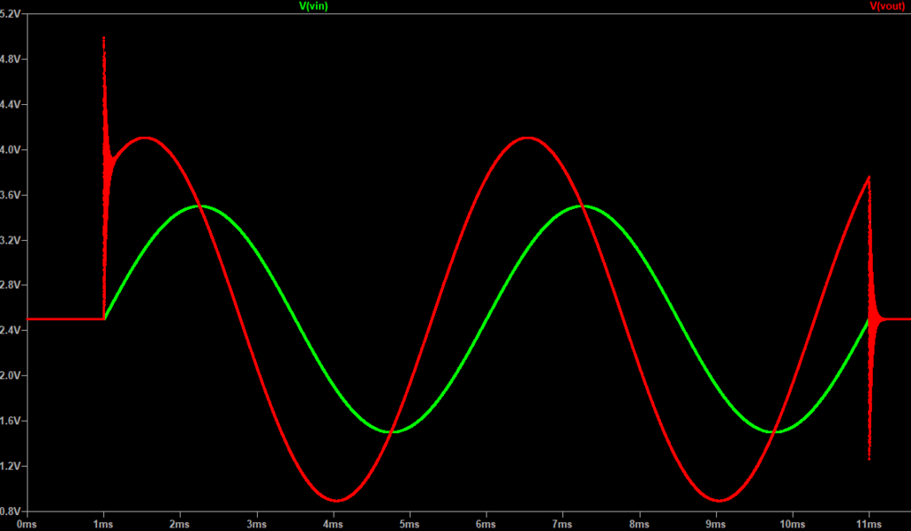
It will be clear that due to this behavior of the amplifier the “ideal” input square wave appears distorted at the output. For example, the rise time Tr is not 0 but has a certain value. The more harmonics are amplified “linearly” (in the right way: same amplification factor and phase shift), the better the result and the shorter the rise time Tr at the output. The value of Tr depends on the frequency of the harmonics, which are of course determined by the frequency of the square wave.
It can thus be stated that the shorter the rise time Tr of the output pulse as a response to an ideal input pulse, the more harmonics are amplified linearly and the higher the bandwidth B of the amplifier. It can be shown that for an amplifier with a bandwidth B, the rise time Tr is related to it according to
BTr = 0.35
where B = bandwidth, Hz
Tr = rise time, S
Example: For the Philips 50-MHz oscilloscope PM 3240, the rise time is
0.35
Tr= 50 X 106 S
= 7 ns
This oscilloscope thus shows a 7-ns rise time as a response to an “ideal” input square wave. As a matter of fact, this is the way the oscilloscope is tested. A pulse for which Tr <<7ns[for example, Tr = l00ps(= 10-10 s)], is applied to the input, and the rise time is measured from the screen.
References
https://www.eetimes.com/document.asp?doc_id=1276244
https://www.edn.com/design/test-and-measurement/4442988/Oscilloscope-rise-time-and-noise-explained
A monthly email packed with valuable content—industry news, tutorials, obsolescence updates, and more. No sales pitches, just insights we think you'll find helpful!
The National Instruments PXI-5441 is a powerful PXI waveform generator designed to support high-speed waveform downloads up...

Companies in almost every industry are being transformed by artificial intelligence, and autonomous machines are...
The PXIe Platform from National Instruments offers an incredibly valuable toolset for test and measurement innovation. Its...

It is no secret that simulation and testing is an important part of designing circuits....