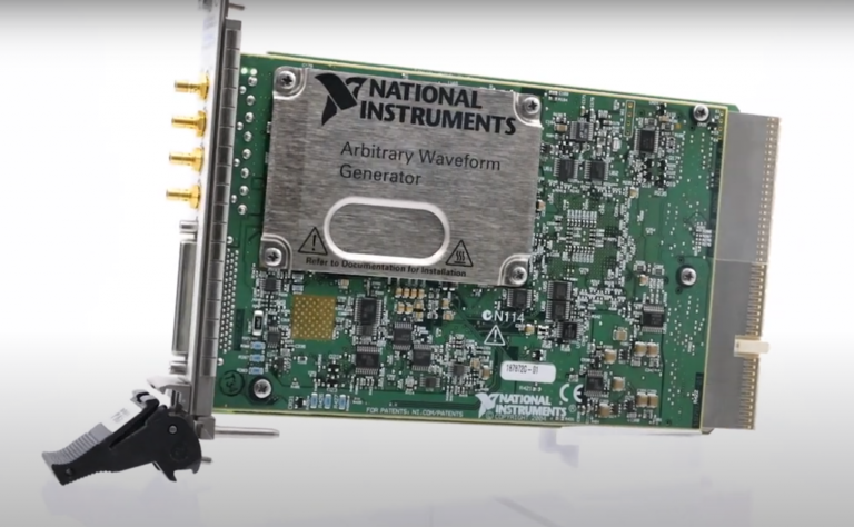
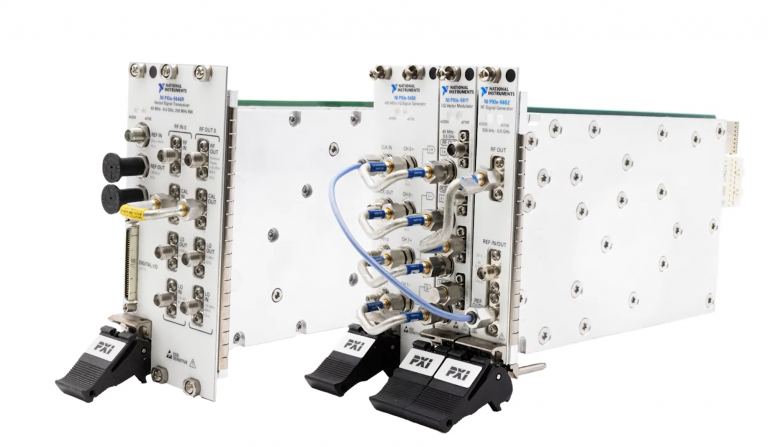
Setup and Optimize the National Instruments PXI-5441 Waveform Generator
The National Instruments PXI-5441 is a powerful PXI waveform generator designed to support high-speed waveform downloads up...
October 25, 2024
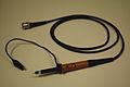
CURRENT PROBES
Basically, the current probe is a transformer of which the primary winding is the test lead through which the current is measured. The probe head consists of a ferrox-cube core and the secondary windings of the transformer. The core can be split into two parts to clip it simply around the measuring lead. The white-colored part of the probe head can be moved backward and forwards to clip it around the lead. A voltage is developed in the transformer secondary windings by the magnetic field around the measuring lead. This voltage is fed to an amplifier box, the output of which is fed to the oscilloscope. The output cable from the amplifier must be terminated with 50 fl at the oscilloscope end (low-ohmic system for 75-MHz bandwidth). Furthermore, if the oscilloscope is set to 50-mV/ div sensitivity, the amplifier box provides calibrated outputs ranging from 1 mA/ div on the screen.

Applications for current probes include:
LOGIC TRIGGER PROBE
In the more sophisticated digital practice, it frequently happens that the engineer wants to trigger an oscilloscope on a word or combination of bits (simultaneously) present at several lines, for example, in a BCD parallel output of a frequency counter. Word recognizers, suitable for use in conjunction with oscilloscopes, are readily available as a kind of probe. Usually, they have several inputs complying with tetrad or octad length (4 or 8). A binary word can be set by switches, and if this word is detected, the unit initiates a trigger which can be used to start a sweep. Alternatively, the trigger can be used to initiate a sweep after a certain delay time by making use of the digital or analog delayedsweep facility. In this way, the display can be started on a recognizable byte, character, or any unique combination of data in logic circuits. For example, the start of the display can be made to coincide with a control byte coming from a peripheral or a BCD output of a decade counter.
References
https://www.eevblog.com/forum/beginners/how-to-measure-current-on-an-oscilloscope/
https://sciencing.com/measure-current-oscilloscope-6828584.html
https://www.electronicdesign.com/test-measurement/11-myths-about-oscilloscope-probes
A monthly email packed with valuable content—industry news, tutorials, obsolescence updates, and more. No sales pitches, just insights we think you'll find helpful!
The National Instruments PXI-5441 is a powerful PXI waveform generator designed to support high-speed waveform downloads up...

Companies in almost every industry are being transformed by artificial intelligence, and autonomous machines are...
The PXIe Platform from National Instruments offers an incredibly valuable toolset for test and measurement innovation. Its...

It is no secret that simulation and testing is an important part of designing circuits....