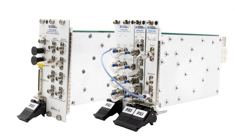
Setup and Optimize the National Instruments PXI-5441 Waveform Generator
The National Instruments PXI-5441 is a powerful PXI waveform generator designed to support high-speed waveform downloads up...
October 25, 2024

Ohm’s Law, discovered by Georg Simon Ohm and first published in 1827, is the earliest and arguably most important connection between current, voltage, and resistance. A straightforward and practical technique for studying electric circuits, Ohm’s Law is very commonly used and has been documented on a broad range of scales. For aspiring electrical engineers studying the basics or for seasoned professionals looking to refresh their knowledge, this scientific law is worth having a deep understanding of.
Resistance refers to the resistance of motion / amount of friction present as free electrons pass across conductors. The quantity of current in a circuit is determined by the voltage available to drive the electrons as well as the degree of resistance in the circuit to prevent electron flow. Resistance, like voltage, is a quantity that exists between two places. As a result, voltage and resistance values are frequently expressed as “between” or “across” two locations in a circuit. In order to make meaningful assertions about these characteristics in circuits, we need to be able to quantify them similarly to how we would for temperature, length, or any physical property.
For this reason, specific measurements are used.
> Current is measured in Ampere, or “Amps”.
> Voltage is measured in Volts.
> Resistance is measured in Ohms.
E = 1R
Where voltage (represented by E), is equal to the current (represented by I) multiplied by the resistance (represented by R). This equation can be re-written to solve for either I or R:
I = E/R or R = E/I
Broadly defined, power refers to the metric that measures how quickly a certain quantity of work is completed. Within the context of circuitry, power is defined as a function of voltage and current in electric circuits. This is outlined using the equation
P = IE
In which P is representative of power, which is equal to the current multiplied by the voltage. The unit of measurement for power is measured in watts.
The mathematical link between the dissipation of power and current through a resistance was discovered by a man named James Prescott Joule. Published in 1841, this finding became known as Joule’s Law, and is represented by the equations of:
P = I2R, P = IE, and P = E2/R
Although estimated power ratings may be calculated from the physical dimensions of the resistor(s) in question, resistor resistance ratings cannot. The greater the resistor, the more it can properly dissipate power without causing harm to the circuit.
A load is defined as any equipment that uses electricity to accomplish a beneficial purpose. In schematic designs, resistor symbols are sometimes used to signify a non-specific load rather than one of a real resistance.
The information and formulas in the post are derived from Chapter 2 of “Lessons in Electric Circuits – Volume 1” by Tony R. Kuphaldt under the design science license. https://www.gnu.org/licenses/dsl.html
A monthly email packed with valuable content—industry news, tutorials, obsolescence updates, and more. No sales pitches, just insights we think you'll find helpful!

The National Instruments PXI-5441 is a powerful PXI waveform generator designed to support high-speed waveform downloads up...

Companies in almost every industry are being transformed by artificial intelligence, and autonomous machines are...
The PXIe Platform from National Instruments offers an incredibly valuable toolset for test and measurement innovation. Its...

It is no secret that simulation and testing is an important part of designing circuits....