Setup and Optimize the National Instruments PXI-5441 Waveform Generator
The National Instruments PXI-5441 is a powerful PXI waveform generator designed to support high-speed waveform downloads up...
October 25, 2024
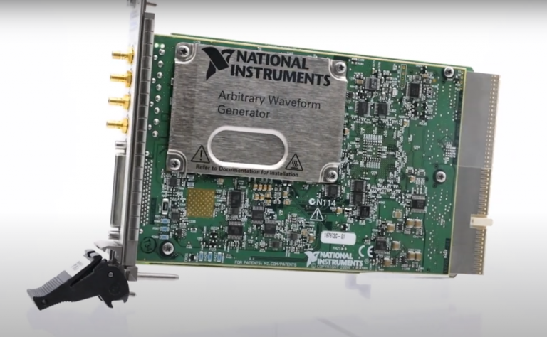
The National Instruments PXI-5441 is a powerful PXI waveform generator designed to support high-speed waveform downloads up to 100 MB/s, making it ideal for complex signal testing and waveform generation tasks. The PXI-5441 allows users to precisely create and change signals, ranging from basic sine waves to complicated I/Q signals for advanced applications, thanks to its strong onboard signal processing capabilities and variety of memory configurations.
In this article, we will guide you through each step of setting up and optimizing the PXI-5441 for maximum performance in your test environment. Whether you’re new to PXI waveform generation or looking to expand your equipment’s capabilities, this guide will walk you through the essential setup, features, and configuration options for easy operation.
The National Instruments PXI-5441 is a high-performance PXI waveform generator, designed for applications that demand rapid waveform generation and precise signal control. This generator is perfect for tasks demanding fast data transfers and effective signal processing because it can download waveforms at up to 100 MB/s.
The PXI-5441 is adaptable for synchronizing with other PXI instruments in intricate, multi-channel test setups since it enables mixed-signal testing. In a range of engineering domains, the PXI-5441 allows customers to generate precise and dependable signals for research, development, or advanced testing applications.
Shop the National Instruments PXI-5441 In Stock at Apex Waves here!
The front panel of the PXI-5441 is equipped with several connectors, each serving a unique purpose in enabling high-quality signal generation and synchronization.
•CH 0: This primary output channel allows the PXI-5441 to generate analog waveforms, directly connecting to external devices for testing and signal processing.
•CLK IN: This clock input SMB jack is designed for external clock synchronization, enabling users to align the PXI-5441’s output with other devices or systems in a testing environment.
•PFI 0 and PFI 1: The Programmable Function Interface (PFI) connectors allow for versatile triggering and event synchronization, offering additional flexibility when coordinating with other PXI instruments or external devices.
•68-pin VHDCI Digital Data and Control Connector: This high-density connector supports digital data transfer and control functions, providing an interface for intricate data and control exchanges that enhance signal testing setups, particularly in multi-channel configurations.
The PXI-5441 waveform generator is available in three memory configurations—32 MB, 256 MB, and 512 MB—each catering to different application needs and data handling capacities. The 32 MB model (model number 779058-02) is well-suited for basic waveform generation tasks or applications that don’t require extensive waveform storage, such as standard sine or square wave testing. This configuration is ideal for users focused on simpler signal testing where high memory is less critical.
The 256 MB model (779058-03) offers a notable boost in waveform memory for more complicated applications, which makes it perfect for jobs requiring faster data flow or more complex waveforms, such as mixed-signal testing in R&D settings. Applications requiring synchronization with other PXI modules or frequent waveform alterations can benefit from this model’s flexibility.
The 512 MB variant (779058-04) can handle lengthy testing sequences and intricate, high-resolution waveforms, making it ideal for the most demanding applications. In situations where long-duration signal production is necessary, such telecommunications testing or I/Q signal generation for radio frequency applications, this approach is especially helpful. The 512 MB version is the best option for complex, memory-intensive testing settings because of its increased memory capacity, which allows for fine control and modification of waveform data.
To ensure accuracy, the National Instruments PXI-5441 must be identified, self-tested, and calibrated before being set up in NI MAX. To ensure a seamless configuration process, adhere to following steps:
1. Open NI Measurement & Automation Explorer (NI MAX)
Launch NI MAX from your desktop or applications menu. This software allows you to configure and test connected National Instruments hardware, including the PXI-5441.
2. Device Identification
In NI MAX, locate the Devices and Interfaces section on the left-hand panel.
Expand this section to view a list of all recognized National Instruments devices. Find the PXI-5441, which should appear under PXI System if it is correctly connected to your PXI chassis.
Select the PXI-5441 from the list to view detailed information, including its model, serial number, and memory size.
3. Performing a Self-Test
With the PXI-5441 selected, click on the Self-Test option. This function checks the device’s basic functionality and verifies that it can communicate with NI MAX.
Once complete, NI MAX will confirm whether the self-test was successful. If any issues arise, check the connections and ensure the device is installed correctly.
4. Running Self-Calibration
After a successful self-test, proceed to Self-Calibration. This step adjusts the PXI-5441’s settings to account for environmental factors, improving accuracy.
Click the Self-Calibrate button, and follow any on-screen prompts to initiate the calibration process. This calibration takes only a few minutes, but it’s essential for maintaining high signal integrity.
Once the calibration is finished, NI MAX will confirm completion and display any calibration data, allowing you to verify that the device is fully calibrated.
5. Saving the Configuration
After successful self-test and calibration, save your configuration within NI MAX to ensure these settings remain applied each time you use the PXI-5441.
This configuration can now be utilized in NI software applications for generating and testing waveforms.
The FGEN Soft Front Panel offers an easy-to-use interface for modifying signal characteristics, including as frequency, waveform type, and amplitude, in order to control the PXI-5441 and personalize waveform settings. This is a detailed tutorial on how to access and utilize the FGEN Soft Front Panel:
1. Open the FGEN Soft Front Panel
After configuring the PXI-5441 in NI MAX, open the FGEN Soft Front Panel. This application can typically be launched directly from NI MAX by selecting the PXI-5441 under Devices and Interfaces, then clicking on Soft Front Panel in the menu.
Alternatively, if the FGEN Soft Front Panel software is installed, you can open it directly from your computer’s application list.
2. Select Waveform Type
Once the Soft Front Panel is open, navigate to the Waveform Type menu to choose the waveform you need. Available options typically include Sine, Square, Triangle, and Sawtooth.
Select your desired waveform type, which will be displayed in the panel.
3. Adjust Frequency Settings
In the frequency control field, you can set the frequency of your waveform. Enter your desired frequency value directly, or use increment/decrement buttons if available.
The PXI-5441 can generate frequencies up to 43 MHz, ideal for a wide range of testing applications.
4. Set Amplitude
Locate the Amplitude control to adjust the output signal’s strength. Enter the amplitude value in volts peak-to-peak (Vpp) or adjust using available controls to suit your test requirements.
5. Fine-Tuning Settings and Visualization
After adjusting your settings, you can view the generated waveform in real time on the display panel. Make any fine adjustments to the frequency, amplitude, or waveform type to match the exact signal specifications needed for your application.
The Synchronization and Memory Core (SMC) architecture from National Instruments is used by the PXI-5441 to provide accurate, multi-channel, phase-coherent outputs that are necessary for sophisticated mixed-signal testing. By lining up their sample clocks and trigger signals, the SMC design enables smooth synchronization between the PXI-5441 and other PXI modules, including digitizers or digital waveform analyzers.
Users can construct an established testing environment to concurrently generate and capture phase-aligned signals by synchronizing the PXI-5441 with a PXI digitizer. This is a crucial prerequisite for I/Q signal processing in RF and communication testing. By enabling extremely accurate simulations and analyses, this phase-coherent generating capability guarantees that test systems are dependable and consistent across a variety of channels.
Applications requiring accurate signal production, including I/Q signal generation for RF communications, where phase coherence is crucial, are where the PXI-5441 shines. In order to modulate and demodulate complicated signals for communications testing and radar applications, I/Q signal production entails producing in-phase (I) and quadrature-phase (Q) signals.
Users can achieve phase-coherent outputs across many channels by installing several PXI-5441 modules, ensuring that all signals are precisely synchronized in timing and phase. In applications like phased-array radar testing and multi-channel communication systems, where preserving signal phase integrity is essential for precise system operation, this is especially helpful. More complex testing and development of wireless communication technologies are made possible by the high-fidelity signal simulations made possible by numerous PXI-5441 modules that can precisely synchronize outputs.
What Can You Do With a Waveform Generator?
Waveform generators are used to apply certain analog signals, such as DC signals, AM/FM modulated signals, sine waves of different frequencies, and more, to circuits. This tutorial describes how to utilize WaveForms’ Waveform Generator tool. Another name for this device is the Wavegen.
What is the Purpose of an Arbitrary Waveform Generator?
In essence, arbitrary waveform generators are advanced playback systems that produce waveforms based on digital data that has been recorded and depicts the continuously fluctuating voltage levels of an AC signal. Instead of using preset common waveforms, these instruments are usually used to create bespoke compiled waveforms.
What Is the Function of a Waveform Generator in Radar?
The transmitting signal is created on an IF-frequency using a waveform generator. It makes it possible to drive the amplitudes and phase shifts of conveyed microwave signals in order to create specified waveforms.
Be sure to browse our blog and YouTube channel for more resources, how-to guides, and trending topics in the tech and legacy test equipment world!
A monthly email packed with valuable content—industry news, tutorials, obsolescence updates, and more. No sales pitches, just insights we think you'll find helpful!
The National Instruments PXI-5441 is a powerful PXI waveform generator designed to support high-speed waveform downloads up...

Companies in almost every industry are being transformed by artificial intelligence, and autonomous machines are...
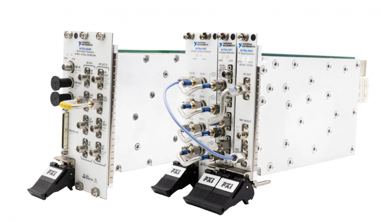
The PXIe Platform from National Instruments offers an incredibly valuable toolset for test and measurement innovation. Its...

It is no secret that simulation and testing is an important part of designing circuits....