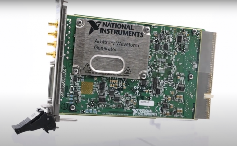
Setup and Optimize the National Instruments PXI-5441 Waveform Generator
The National Instruments PXI-5441 is a powerful PXI waveform generator designed to support high-speed waveform downloads up...
October 25, 2024

It is no secret that simulation and testing is an important part of designing circuits. Due to the high costs of photolithographic masks and additional production materials, it is highly preferred to have integrated circuits as close to perfect as possible before they are constructed. Integrated circuits cannot be breadboarded prior to production (unlike board-level designs made up of discrete pieces), so what is the best way to simulate them? The solution comes in the form of the computer program SPICE (Simulation Program with Integrated Circuit Emphasis).
According to the official website, SPICE “is a general-purpose circuit simulation program for nonlinear dc, nonlinear transient, and linear ac analyses”. Put simply, it is a computer program that has been designed to replicate and simulate analog electronic circuits (specifically integrated circuits) as well as to predict the behavior of low- to mid- frequency circuits.
The story of SPICE begins at the University of California, Berkeley in the late 1960s. A professor named Ronald Rohrer, along with a group of his students, developed a circuit simulation program called CANCER (Computer Analysis of Nonlinear Circuits, Excluding Radiation). When Rohrer eventually left U.C. Berkeley, CANCER was rewritten by Laurence Nagel and Professor Donald Pederson, who was adamant on releasing the newly named SPICE program into the public domain so that anyone could use and improve upon it. The first version of SPICE was released into the public domain in 1972. The latest version, version 3, was initially released in the 1980s. This new version of the program included a greater variety of transistors and switches, and was created using the C language rather than FORTRAN.
Circuit simulation allows you to identify any errors early on in the creation process, avoiding costly and time-consuming re-prototyping. SPICE simulation works by first assigning nodes to the circuit, creating an equation matrix, and then solving for the values of these nodes using either Kirchhoff’s Law of Current or Voltage. The number of iterations needed by the SPICE simulator to solve the nodal equations will vary depending on the kind of circuit.
What does this programming look like practically? Because SPICE is what is known as an “interpreted language”, the SPICE program must be installed on the computer in order to interpret the input. Source files for SPICE are referred to as “netlists”, and they are written descriptions of every component of the circuit, including transistors, capacitors, and their associated connections. The netlist follows the rules of a simple programming language.
The general-purpose nature of SPICE allows for a variety of analyses, including:
DC Analysis, which determines the DC operating point of the circuit when it has shorted inductors and open capacitors.
AC Small-Signal Analysis, which is when the circuit’s AC output can be calculated as a function of the frequency.
Transient Analysis, which examines the varying transient output variables over a specific time frame (dictated by the user) to give insight into how the values change over time.
Pole-Zero Analysis, which is used to evaluate the zeros and/or poles in an ac transfer function with small signals.
Small-Signal Distortion Analysis, which is used to calculate intermodulation and other products when the input signals are at lower magnitudes.
Sensitivity Analysis, which makes calculations related to operating-point sensitivities or AC small-signal sensitivities, which can be done for any output variable and covers all circuit variables and model parameters.
Noise Analysis, which is used to simply examine noise generated from the specified circuit.

SPICE is incredibly reliable and straightforward to use, especially for basic circuits. It can simulate a wide variety of components, from the simplest passives such as resistors and capacitors to sophisticated semiconductor devices such as MESFETs and MOSFETs. By using these embedded components as building blocks for large-scale models, designers and chip makers have been able to define a truly multitude of different SPICE models.
One such model is the Multisim™ Electronics Workbench™ from NI. Multisim™ uses a user-friendly graphic interface combined with advanced SPICE simulation to quickly see and understand the behavior of electrical circuits, The Multisim™ software is available for applications from education to professional design, enabling researchers and designers to cut the number of printed circuit board (PCB) prototype iterations and development expenses by integrating robust circuit simulation and analysis into the design cycle.
A monthly email packed with valuable content—industry news, tutorials, obsolescence updates, and more. No sales pitches, just insights we think you'll find helpful!
The National Instruments PXI-5441 is a powerful PXI waveform generator designed to support high-speed waveform downloads up...

Companies in almost every industry are being transformed by artificial intelligence, and autonomous machines are...
The PXIe Platform from National Instruments offers an incredibly valuable toolset for test and measurement innovation. Its...
It is no secret that simulation and testing is an important part of designing circuits....