Setup and Optimize the National Instruments PXI-5441 Waveform Generator
The National Instruments PXI-5441 is a powerful PXI waveform generator designed to support high-speed waveform downloads up...
October 25, 2024
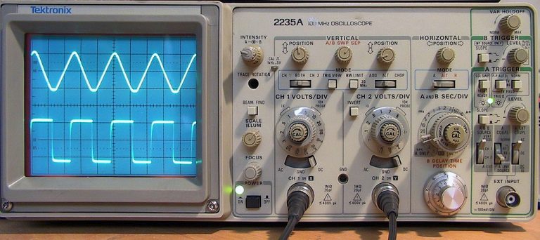
Storage oscilloscopes are used in applications where the display time at the screen is too short to examine the signals to be measured. If a single-shot signal is to be measured, only one sweep is generated. During this sweep, the screen is excited by the high-energy electron beam. When the beam is suppressed at the end of the single sweep, a phosphorescence remains for some time. The time that the phosphorescence remains visible is dependent upon the type of phosphor used and is referred to as the persistence of the tube. The persistence is the time that the intensity, after the excitation, takes to decay to a level of I/ e of the level attained during excitation (e = 2.72 = base of natural logarithms).
A storage CRT can extend the persistence time in excess of minutes. The storage principle is based on the phenomenon of secondary emission. Furthermore, for the storage layer a composition is used which possesses not only good secondary emission but also good isolation against cross-migration of electric charge of the particles loaded by secondary emission. Various compositions may be used, such as:
When the electron beam of the CRT hits the layer of particles of the composition with the high energy caused by the acceleration voltage, more secondary electrons are emitted from the particles than are captured from the primary electrons that have hit them. Thus, bombarded particles become positively charged. Due to the insulation property, the pattern written by the high-energy beam remains as a charge pattern at the layer. This charge pattern is later used to visualize the pattern again. For this purpose, special techniques have been developed for storage CRTs.

The Bistable Cathode-Ray Tube
The first commercially available storage CRT was the bistable cathoderay tube (Tektronix). Here the phosphor used for the screen is applied in scattered particles to avoid cross-migration of the stored charge. The layer of scattered phosphor may be more than one particle thick to give a homogeneous display on the screen.
Before the phosphor is deposited on the screen, a transparent metal film is first deposited on the inside surface. This conductive layer acts as a controlling electrode. The writing beam- the focused high-energy beam of the CRT electron gun- hits the particles with such an energy that a charge pattern is caused, as already described. To visualize this pattern again after writing, a cloud of low-energy electrons is sent towards the screen from a pair of food guns in the CRT. The shape and speed of this low-energy cloud are controlled by the voltage of the transparent metal layer. On those parts of the screen where the particles have a positive charge, the energy of the flood-gun electrons is sufficient to illuminate the phosphor. On all the other parts of the screen, the lowenergy electrons do not have enough energy to illuminate the phosphor. They are repelled and must be collected by the metal film in the cone of the tube collimator. In this way, a replica of the formerly written waveform is achieved. This type of storage CRT is said to be of a bistable nature; that is, no halftones are possible.
An advantage of this system is the ability to split up the metal film backplate into upper and lower halves. Therefore, for comparison purposes, a waveform can be stored in the upper half of the screen, while the lower half can be used in the normal mode for the user’s measurements.
Construction of the Variable-Persistence Tube
The second type of storage tube is the mesh storage tube, which makes use of a dielectric material deposited on a storage mesh as a target. The mesh is located between the deflection plates and the normal standard phosphor screen of the CRT, about 6 mm in front of the screen when viewed from the deflection plates.
The mesh storage tube works on much the same principle as the bistable tube. Positively charged areas of the storage target allow electrons from the flood guns to pass through the mesh towards the standard phosphor, thereby reproducing the stored replica. As this type of storage tube is the most widely used, its construction is described in somewhat more detail.
The storage CRT contains two systems: the writing system and the flood system. The construction and operation of the writing system are identical to that of a conventional CRT. The flood system consists of a pair of flood guns operated in parallel, both having a cathode, a control grid, and an accelerator grid. Common to both flood guns are the flood-beam collimator, the collector mesh, the storage mesh carrying the storage layer, and the phosphor viewing screen with its aluminized layer.
References
https://www.radiomuseum.org/forum/tektronix_three_kinds_of_storage.html
https://www.electronicdesign.com/displays/robert-h-anderson-putting-storage-oscilloscopes
A monthly email packed with valuable content—industry news, tutorials, obsolescence updates, and more. No sales pitches, just insights we think you'll find helpful!
The National Instruments PXI-5441 is a powerful PXI waveform generator designed to support high-speed waveform downloads up...
Companies in almost every industry are being transformed by artificial intelligence, and autonomous machines are...
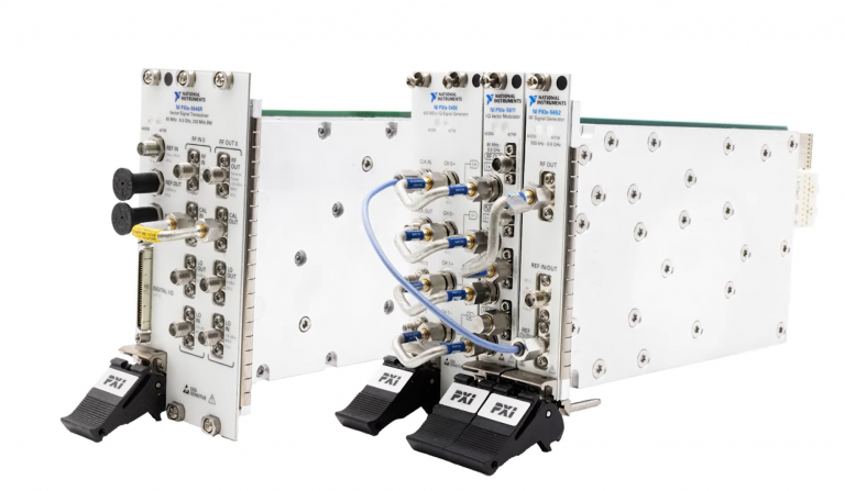
The PXIe Platform from National Instruments offers an incredibly valuable toolset for test and measurement innovation. Its...

It is no secret that simulation and testing is an important part of designing circuits....