Setup and Optimize the National Instruments PXI-5441 Waveform Generator
The National Instruments PXI-5441 is a powerful PXI waveform generator designed to support high-speed waveform downloads up...
October 25, 2024
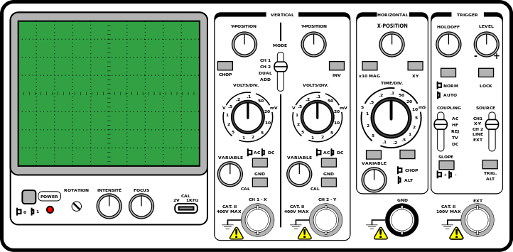
The 15-MHz portable dual-trace oscilloscope Philips PM 3226 is a compact, lightweight instrument featuring simplicity of operation, for a wide range of use in servicing, research, and educational applications. Other features include provision for chopped or alternate display of Y signals, automatic triggering, mains triggering, and triggering on the line and frame sync pulses of a television signal. The cathode-ray tube displays a useful screen area calibrated into 8 x 10 divisions by an external graticule.
All circuits are fully transistorized and mounted on printed circuit boards for ease of maintenance. The straightforward design and layout combine simple operation with a high degree of reliability.
The PM 3240 portable hf oscilloscope enables the measurement of signals at a high sensitivity (5 mV/div) over a large bandwidth (50 MHz). There is a wide choice of display possibilities, such as one channel, two channels alternately or chopped, two channels added, with normal and inverted position for one input signal, and a main and delayed time base. The PM 3240 oscilloscope features a tapless power supply with low dissipation. This power supply works on any ac mains voltage between 90 and 264 V, or any dc voltage between 90 and 200 V, thus obviating the need for adjusting the instrument to the local mains voltage. All these features make the oscilloscope suitable for a wide variety of applications.
Characteristics
This specification is valid after the instrument has warmed up for 15 minutes. Properties expressed in numerical values with tolerances stated are guaranteed by the manufacturer. Numerical values without tolerances are typical and represent the characteristics of an average instrument.
Generally, for the more sophisticated oscilloscopes additional information is given, particularly regarding the conditions under which the specifications are valid.
ADDITIONAL NOTES TO THE SPECIFICATIONS
Besides the bandwidth of an amplifier, the “phase characteristic” also is of utmost importance. The phase characteristic shows the phase shift between the input and output signal as a function of the frequency. Mathematically, it can be proved that for an “ideal” amplifier response both the phase and the frequency characteristic must be Aat. However, an “idea” phase behavior is related to the frequency response.
For X-Y measurements, the importance of the phase characteristics becomes obvious. If the X and Y amplification channels show different characteristics, then, without any phase shift in the signals to be measured (for example, the same signal), a phase shift is nevertheless displayed on the screen, usually at the higher frequencies. The reason for this is because the Y channel includes a delay line, whereas the X channel does not. The fraction of the Y axis cut off by the ellipsoid denotes sin cp, with cp being the phase shift in degrees.
Environmental testing is often referred to as testing an apparatus according to M2C1 or M2C2 rules. With few exceptions, this statement is meaningless to the customer. In the case of the Philips PM 3240 oscilloscope, slightly more is specified. The specifications state that the requirements are fulfilling the IEC 68 Db recommendation, which does not say very much. For this reason, a glossary of operation conditions and test procedures for operating, storage, and handling is given.

What Does IEC Mean?
IEC stands for the International Electrotechnical Commission, which is affiliated to the International Organization for Standardization (ISO). The standards recommended by the IEC include:
These standards are important because every manufacturer who follows the IEC recommendations is specifying the same type of products in the same way, and this results in more clarity for the customers. Also, the Philips Product Division for Scientific and Industrial Equipment (S&I) follows the IEC recommendations, and a Quality Manual detailing the IEC requirements is binding within the S&I Division.
References
https://www.shopyourway.com/questions/1064567
https://www.radio-electronics.com/info/t_and_m/oscilloscope/oscilloscope-specs-specifications.php
A monthly email packed with valuable content—industry news, tutorials, obsolescence updates, and more. No sales pitches, just insights we think you'll find helpful!
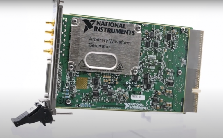
The National Instruments PXI-5441 is a powerful PXI waveform generator designed to support high-speed waveform downloads up...

Companies in almost every industry are being transformed by artificial intelligence, and autonomous machines are...
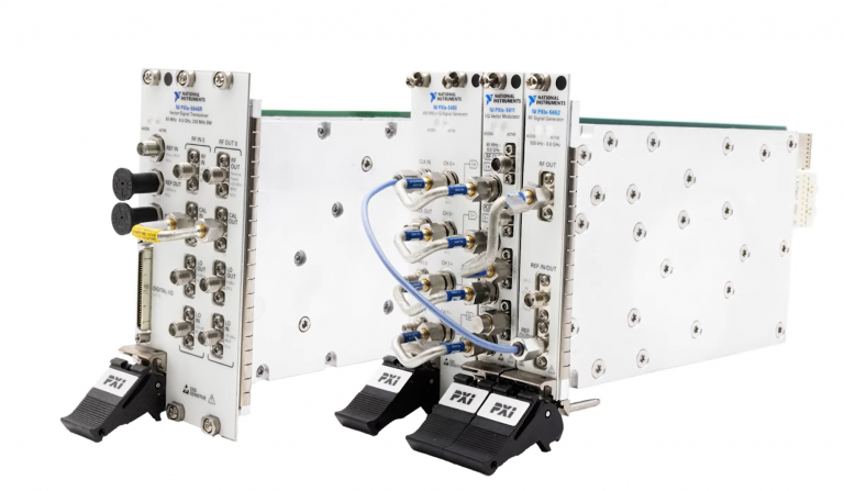
The PXIe Platform from National Instruments offers an incredibly valuable toolset for test and measurement innovation. Its...

It is no secret that simulation and testing is an important part of designing circuits....